LAYER 2 Vlan, Spanning-tree, Trunk, EtherChannel, and Dot1Q Encapsulation
Published on 12 min read
Updated on
In this series39 min read in total
- LAYER 2 Vlan, Spanning-tree, Trunk, EtherChannel, and Dot1Q Encapsulation
- LAYER 3 Static Routing, RIPv2, OSPF, NAT
- The hierarchy of CLI cisco
- Help, autocompletion, monitoring, shortcuts
- Alcatel Switch Configuration
- Remote Access
A switch out of the box is one single, wide broadcast domain: everything plugged into it can see, hear and receive everyone else’s broadcasts. The five features in this article correct that behaviour, and each one answers the problem created by the previous one.
| Feature | The problem it solves |
|---|---|
| VLAN | a single switch lumps everyone into the same broadcast domain |
| Trunk | a segmented VLAN does not cross the boundary between two switches |
| Spanning-tree | wiring switches together creates loops that saturate the network |
| EtherChannel | a single link between switches is both a bottleneck and a single point of failure |
| Dot1Q encapsulation | properly separated VLANs cannot talk to each other at all |
We will follow that chain in order.
VLANs: segmenting the switch
A VLAN splits a physical switch into several logical switches. Ports in a VLAN only see other ports in the same VLAN, which brings three immediate benefits.
- Security: workstations in one department can no longer listen to another department’s traffic.
- Performance: broadcasts stay contained, the broadcast domain shrinks accordingly.
- Cost and flexibility: one switch replaces several separate devices, and moving a workstation to another department takes one command, with no cabling change.
Create the VLAN
Switch(config)# vlan 10name ACCOUNTINGThe name is optional but strongly recommended: six months from now,
VLAN0010will mean nothing to anyone.Assign a port to the VLAN
Switch(config)# interface FastEthernet0/1Switch(config-if)# switchport mode accessswitchport access vlan 10Interface
Fa0/1now belongs to VLAN 10.Verify
Switch# show vlan briefThis command lists existing VLANs and the ports assigned to each. It is the check to run before looking any further when two machines cannot see each other.
The no prefix deletes a VLAN:
no vlan 10The segmentation works, as long as everything fits on one switch. As soon as there are two, VLAN 10 stops at the boundary.
Trunks: letting VLANs cross the boundary
A trunk link carries several VLANs over one cable between two devices. Put another way, it extends each VLAN from one switch to the other, as if the two were only one.
| Physical view | Logical view |
|---|---|
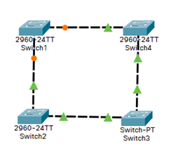 |  |
To tell VLANs apart on a single cable, the switch adds a 4-byte tag to each frame, carrying the VLAN number. This is the IEEE 802.1Q standard, also called dot1Q. The switch on the far side reads the tag, strips it, and puts the frame back into the right VLAN.
Switch the port to trunk mode
Switch(config)# interface FastEthernet0/1Switch(config-if)# switchport mode trunkLimit the carried VLANs
Switch(config-if)# switchport trunk allowed vlan 10,20,30By default, a trunk carries every VLAN. Restricting the list keeps a sensitive VLAN from wandering onto links that have no use for it, and cuts broadcast traffic across the network.
Verify
Switch# show interfaces trunkThe output confirms the mode, the encapsulation, the native VLAN and the list of VLANs actually allowed and active on the link.
VLANs now cross several switches. But adding a second cable between them for redundancy brings the network down.
Spanning-tree: surviving loops
An Ethernet frame carries no time-to-live counter, unlike an IP packet. A broadcast frame caught in a physical loop therefore circles forever, duplicates at every switch it crosses, and saturates the whole network within seconds. This is the broadcast storm, and it makes the network entirely unusable, not merely slow.
The Spanning Tree Protocol (STP) solves this without removing cables: it computes a loop-free topology and logically blocks the extra links, keeping them ready to take over if the main one goes down.
That is why the priority gets configured explicitly.
spanning-tree vlan 10 priority 8000% Bridge Priority must be in increments of 4096.% Allowed values are:0 4096 8192 12288 16384 20480 24576 2867232768 36864 40960 45056 49152 53248 57344 61440Two commands save you from doing the arithmetic yourself:
spanning-tree vlan 10 root primaryspanning-tree vlan 10 root secondaryThe first lowers the priority just enough to win the election, the second designates a stand-in that takes over if the first goes down.
Each port is then given a role, visible with show spanning-tree:
| Role | Meaning |
|---|---|
| Root | the port leading to the root bridge over the best path |
| Designated | the port serving a segment, downstream of the root |
| Blocking or Alternate | the port put on hold to break the loop |
The network now supports redundancy. Except the backup link sits idle as long as the main one works.
EtherChannel: aggregating links rather than blocking them
Spanning-tree solves loops by wasting bandwidth: with two cables between two switches, only one works. EtherChannel changes that by presenting several physical links as one single logical link, which STP sees as unique and therefore does not block.
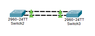
Up to 8 active links can be aggregated. Bandwidth adds up, and losing a cable reduces throughput without ever cutting the link or triggering an STP reconvergence.
Select the interface range
Switch(config)# interface range FastEthernet0/1-2Create the group
Switch(config-if-range)# channel-group 1 mode activeLACP is the open standard (IEEE 802.3ad), the one to prefer. Mode
activenegotiates actively,passivewaits for the other side to offer. At least one side must beactive.Switch(config-if-range)# channel-group 1 mode desirablePAgP is the Cisco proprietary protocol, equivalent to LACP but limited to that vendor’s devices.
desirablenegotiates actively,autowaits.Switch(config-if-range)# channel-group 1 mode onNo negotiation at all: the group is forced on both sides. It works, but if the configuration opposite is incomplete or different, nothing reports it and a loop can form. Keep it for cases where the remote device speaks neither LACP nor PAgP.
The commands must be repeated identically on the second switch.
Verify
Switch# show etherchannel summaryThe
SUflag on the Port-channel means an operational layer 2 group, andPon each interface confirms it does take part in the group.
The network is now segmented, extended, redundant and fast. One thing is missing: the VLANs cannot talk to each other at all.
Dot1Q encapsulation: letting VLANs talk
This is the direct and intended consequence of the first chapter: two VLANs are two distinct networks, and moving from one network to another is routing, hence layer 3. A router is needed.
Rather than dedicating one router port to each VLAN, a single physical link is used as a trunk, split into logical subinterfaces, one per VLAN. That setup is known as router-on-a-stick.
Create the subinterface
Router(config)# interface GigabitEthernet0/0/0.10The suffix after the dot is merely a subinterface number. Reusing the VLAN number is not mandatory, but it is a universal convention that keeps the configuration readable.
Declare the encapsulation
Router(config-subif)# encapsulation dot1Q 10This is where, and only where, the link to VLAN 10 is made. The router will know how to read frames tagged 10 and will tag its own answers the same way.
Address the subinterface
Router(config-subif)# ip address 192.168.10.1 255.255.255.0192.168.10.1becomes the default gateway to configure on every machine in VLAN 10.Bring up the physical interface
Router(config)# interface GigabitEthernet0/0/0no shutdownRepeat for each VLAN
Terminal conf tint g0/0/0.20encapsulation dot1Q 20ip address 192.168.20.1 255.255.255.0exitint g0/0/0no shutendwrite memory
These five mechanisms form the base of any switched enterprise network. The next article in the series moves up to layer 3 and to routing between these now properly separated networks.